
 5秒后页面跳转

| 型号 | 品牌 | 获取价格 | 描述 | 数据表 |
| CAT5114PI-00TE13 | CATALYST |
获取价格 |
32-Tap Digitally Programmable Potentiometer |

|
| CAT5114PI-10 | CATALYST |
获取价格 |
Digital Potentiometer, 1 Func, 10000ohm, Increment/decrement Control Interface, 32 Positio |
|
| CAT5114PI-10TE13 | CATALYST |
获取价格 |
32-Tap Digitally Programmable Potentiometer |
|
| CAT5114PI-20TE13 | CATALYST |
获取价格 |
32-Tap Digitally Programmable Potentiometer (DPP) |
|
| CAT5114PI-50TE13 | CATALYST |
获取价格 |
32-Tap Digitally Programmable Potentiometer |
|
| CAT5114R-00 | CATALYST |
获取价格 |
100K DIGITAL POTENTIOMETER, INCREMENT/DECREMENT CONTROL INTERFACE, 32 POSITIONS, PDSO8, MS |
|
| CAT5114R00TE13 | CATALYST |
获取价格 |
32-Tap Digitally Programmable Potentiometer |
|
| CAT5114R-00TE13 | CATALYST |
获取价格 |
32-Tap Digitally Programmable Potentiometer (DPP) |
|
| CAT5114R-10 | CATALYST |
获取价格 |
10K DIGITAL POTENTIOMETER, INCREMENT/DECREMENT CONTROL INTERFACE, 32 POSITIONS, PDSO8, MSO |
|
| CAT5114R10TE13 | CATALYST |
获取价格 |
32-Tap Digitally Programmable Potentiometer |
|
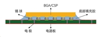 芯片底部填充工艺:提升电子设备可靠性的关键步骤

 REF03GPZ资料解读:主要特征、技术参数、应用场景
 一文带你了解DS28E40主要特征、安全特性、应用场景
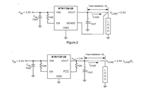 RT9172资料手册解读:关节特性、引脚信息、参数说明
工作时间:9:00-21:00
CEO邮箱:ceo@jiepei.com
投诉邮箱:tousu@jiepei.com


 浙公网安备 33010502006866号 浙ICP备10014259号-119
营业执照ICP证
浙公网安备 33010502006866号 浙ICP备10014259号-119
营业执照ICP证


