Model Selection Guide
www.micropowerdirect.com
Over
Input
Reflected
Ripple
Current
(mA, Typ)
Output
Capacitive Fuse Rating
Model
Number
Voltage Efficiency
Protection (%, Typ)
(VDC)
Voltage (VDC)
Current (mA)
Load
Slow-Blow
(mA)
Voltage Current
Current
(µF Max)
(VDC) (mA, Max) (mA, Min)
Nominal Range Full-Load No-Load
B4001RW
B4002RW
B4003RW
B4004RW
B4005RW
B4006RW
B4011RW
B4012RW
B4013RW
B4014RW
B4015RW
B4016RW
B4021RW
B4022RW
B4023RW
B4024RW
B4025RW
B4026RW
12
12
12
12
12
12
24
24
24
24
24
24
48
48
48
48
48
48
9.0 - 18.0
9.0 - 18.0
9.0 - 18.0
9.0 - 18.0
9.0 - 18.0
9.0 - 18.0
18.0 - 36.0 1,222
18.0 - 36.0 1,832
18.0 - 36.0 1,831
18.0 - 36.0 1,831
18.0 - 36.0 1,872
18.0 - 36.0 1,872
36.0 - 75.0
36.0 - 75.0
36.0 - 75.0
36.0 - 75.0
36.0 - 75.0
36.0 - 75.0
2,472
3,745
3,745
3,703
3,786
3,787
120
160
160
150
70
60
75
50
85
75
50
45
40
50
50
50
65
50
50
50
50
50
50
30
30
30
30
30
30
20
20
20
20
20
20
3.3
5.0
8,000.0
8,000.0
3,333.0
2,666.0
1,666.0
1,333.0
8,000.0
8,000.0
3,333.0
2,666.0
1,666.0
1,333.0
8,000.0
8,000.0
3,333.0
2,666.0
1,666.0
1,333.0
0.0
0.0
0.0
3.9
6.2
89
89
89
90
88
88
90
91
91
91
89
89
90
91
92
92
89
89
21,000
13,600
2,360
1,510
1,200
750
21,000
13,600
2,360
1,510
1,200
750
21,000
13,600
2,360
1,510
1,200
750
8,000
8,000
8,000
8,000
8,000
8,000
4,000
4,000
4,000
4,000
4,000
4,000
2,000
2,000
2,000
2,000
2,000
2,000
12.0
15.0
12.0
15.0
3.3
15.0
18.0
15.0
18.0
3.9
0.0
145.0
110.0
0.0
0.0
0.0
5.0
6.2
12.0
15.0
12.0
15.0
3.3
15.0
18.0
15.0
18.0
3.9
0.0
145.0
110.0
0.0
0.0
0.0
0.0
145.0
110.0
611
916
906
906
936
936
5.0
6.2
12.0
15.0
12.0
15.0
15.0
18.0
15.0
18.0
65
For heatsink option, add suffix “H” to model number (i.e. B4003RW-H)
For Remote Control option, add suffix “R” to model number (i.e. B4003RW-R)
Notes:
ꢀ. Load regulation is specified for a load change of minimum load to full load.
Derating Curve
2. When measuring output ripple, it is recommended that external ꢀ.0 µF & ꢀ0 µF capacitors be placed in parallel
from the +Vout pin to the -Vout pin for single output units and from each output to common for dual output units.
3. Transient recovery is measured to within a ꢀ% error band for a load step change of 75% to ꢀ00%.
4. The maximum control current at the on/off pin (pin 6) during a logic high is 5 µA. The maximum control current to
the on/off pin at logic low is -ꢀ00 µA. If the on/off pin is left open, the unit operates. If igrounded, the unit will shut off.
5. Operation at no-load will not damage these units. However, they may not meet all specifications.
6. Dual output units may be connected to provide a 24 VDC or 30 VDC output. To do this, connect the load across
the positive (+Vout) and negative (-Vout) outputs and float the output common.
7. The converter should be connected to a low ac-impedance source.An input source with a highly inductive imped-
ance may affect the stability of the converter. In applications where the converter output loading is high and input
power is supplied over long lines, it may be necessary to use a capacitor on the input to insure start-up.
In this case, it is recommended that a low ESR (ESR <ꢀ.0 at ꢀ00 kHz) capacitor be mounted close to the
converter. For ꢀ2V input units, a 22.0 µF is recommended; for 24V & 48V units a 6.8 µF.
8. An external resistor may be used to adjust the converter output by ꢀ0%.To adjust the output UP, connect a 5%,
3W resistor between the minus output pin and the Vout trim pin. To adjust the output DOWN, connect a 5%, 3W
resistor between the plus output pin and the V trim pin. For continuous UP/Down trimming capability, connect
a ꢀ0 kW potentiometer between the plus andOmUT inus outputs with the wiper arm connected to the VOUT trim pin.
The trim pin may be left floating if it is not used. Contact the factroy for more information.
9. It is recommended that a fuse be used on the input of a power supply for protection. See the table above for the
correct rating.
Heatsink Dimensions (Optional)
Mechanical Dimensions
Pin Connections
Pin Single
Dual
+Vin
-Vin
1
2
3
4
5
6
+Vin
-Vin
ON/OFF ON/OFF
+Vout
-Vout
Trim
+Vout
Comm.
-Vout
Heatsink Notes:
• The heatsink is black anodized aluminum.
• Heatsink weight is 0.07 Oz (2.0g)
Mechanical Notes:
MicroPower Direct
• All dimensions are typical in inches (mm)
• Tolerance x.xx = 0.0ꢀ ( 0.25)
We Power Your Success - For Less!
292 Page Street Ste D Stoughton, MA 02072
•
TEL: (781) 344-8226
•
FAX: (781) 344-8481
•
E-Mail: sales@micropowerdirect.com


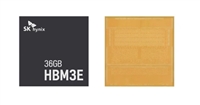
 SK海力士量产12层HBM3E,容量高达36GB

 意法半导体传感器驱动Sphere,开启沉浸式电影新时代

 摩尔斯微电子在美国约书亚树国家公园测试 Wi-Fi HaLow

 贸泽上架Tallysman TW5386智能GNSS天线
