71M6533/71M6534 Data Sheet
FDS_6533_6534_004
Tables
Table 1: Signals Selected for the ADC with SLOTn_SEL and SLOTn_ALTSEL (MUX_DIV = 7) ...................11
Table 2: ADC Resolution.............................................................................................................................11
Table 3: ADC RAM Locations .....................................................................................................................12
Table 4: XRAM Locations for ADC Results ................................................................................................15
Table 5: Inputs Selected in Regular and Alternate Multiplexer Cycles.......................................................15
Table 6: CKMPU Clock Frequencies ..........................................................................................................19
Table 7: Memory Map .................................................................................................................................20
Table 8: Internal Data Memory Map ...........................................................................................................21
Table 9: Special Function Register Map.....................................................................................................22
Table 10: Generic 80515 SFRs - Location and Reset Values....................................................................22
Table 11: PSW Bit Functions (SFR 0xD0) ...................................................................................................23
Table 12: Port Registers .............................................................................................................................24
Table 13: Stretch Memory Cycle Width ......................................................................................................25
Table 14: 71M6533/71M6534 Specific SFRs .............................................................................................25
Table 15: Baud Rate Generation ................................................................................................................27
Table 16: UART Modes...............................................................................................................................27
Table 17: The S0CON (UART0) Register (SFR 0x98).................................................................................28
Table 18: The S1CON (UART1) Register (SFR 0x9B) ................................................................................28
Table 19: PCON Register Bit Description (SFR 0x87) ...............................................................................28
Table 20: Timers/Counters Mode Description ............................................................................................29
Table 21: Allowed Timer/Counter Mode Combinations ..............................................................................29
Table 22: TMOD Register Bit Description (SFR 0x89)................................................................................29
Table 23: The TCON Register Bit Functions (SFR 0x88)............................................................................30
Table 24: The IEN0 Bit Functions (SFR 0xA8)............................................................................................31
Table 25: The IEN1 Bit Functions (SFR 0xB8)............................................................................................31
Table 26: The IEN2 Bit Functions (SFR 0x9A)............................................................................................31
Table 27: TCON Bit Functions (SFR 0x88) .................................................................................................32
Table 28: The T2CON Bit Functions (SFR 0xC8).......................................................................................32
Table 29: The IRCON Bit Functions (SFR 0xC0)........................................................................................32
Table 30: External MPU Interrupts..............................................................................................................33
Table 31: Interrupt Enable and Flag Bits ....................................................................................................33
Table 32: Interrupt Priority Level Groups....................................................................................................34
Table 33: Interrupt Priority Levels...............................................................................................................34
Table 34: Interrupt Priority Registers (IP0 and IP1) ....................................................................................34
Table 35: Interrupt Polling Sequence..........................................................................................................35
Table 36: Interrupt Vectors..........................................................................................................................35
Table 37: Clock System Summary..............................................................................................................37
Table 38: Bank Switching with FL_BANK[2:0] ............................................................................................41
Table 39: Data/Direction Registers and Internal Resources for DIO Pin Groups.......................................43
Table 40: Selectable Resources using the DIO_Rn Bits.............................................................................45
Table 41: EECTRL Bits for 2-pin Interface...................................................................................................47
Table 42: EECTRL Bits for the 3-wire Interface...........................................................................................47
Table 43: SPI Command Description..........................................................................................................50
Table 44: TMUX[4:0] Selections .................................................................................................................52
Table 45: Available Circuit Functions..........................................................................................................56
Table 46: I/O RAM Map – Functional Order ...............................................................................................74
Table 47: I/O RAM Description – Alphabetical (by Bit Name) ....................................................................78
Table 48: CE EQU Equations and Element Input Mapping ........................................................................92
Table 49: CE Raw Data Access Locations .................................................................................................92
Table 50: CESTATUS Register.....................................................................................................................93
Table 51: CESTATUS Bit Definitions............................................................................................................93
Table 52: CECONFIG Register....................................................................................................................93
Table 53: CECONFIG Bit Definitions...........................................................................................................94
Table 54: Sag Threshold and Gain Adjust Control .....................................................................................95
Table 55: CE Transfer Variables.................................................................................................................95
6
© 2007-2009 TERIDIAN Semiconductor Corporation
v1.1


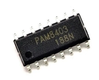
 PAM8403音频功率放大器:资料手册参数分析

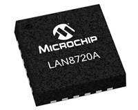
 LAN8720以太网收发器:资料手册参数分析

 SI2301 N沟道MOSFET:资料手册参数分析

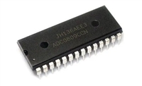
 ADC0809逐次逼近寄存器型模数转换器:资料手册参数分析
