
 5秒后页面跳转

| 是否Rohs认证: | 符合 | 生命周期: | Active |
| 包装说明: | DB1627, 6 PIN | Reach Compliance Code: | unknown |
| ECCN代码: | EAR99 | 风险等级: | 5.74 |
| 特性阻抗: | 75 Ω | 构造: | MODULE |
| 最大输入功率 (CW): | 30 dBm | 最大插入损耗: | 1.3 dB |
| 最大工作频率: | 1000 MHz | 最小工作频率: | 10 MHz |
| 最高工作温度: | 85 °C | 最低工作温度: | -40 °C |
| 射频/微波设备类型: | DIRECTIONAL COUPLER | 最大电压驻波比: | 1.2 |
| Base Number Matches: | 1 |
| 型号 | 品牌 | 获取价格 | 描述 | 数据表 |
| TCD-18-4X+ | MINI |
获取价格 |
Directional Coupler, 5MHz Min, 1000MHz Max, 1.4dB Insertion Loss-Max, ROHS COMPLIANT, CASE |

|
| TCD18AH | ZOWIE |
获取价格 |
SURFACE MOUNT TRANSIENT VOLTAGE SUPPRESSOR |
|
| TCD18CAH | ZOWIE |
获取价格 |
SURFACE MOUNT TRANSIENT VOLTAGE SUPPRESSOR |
|
| TCD190AH | ZOWIE |
获取价格 |
SURFACE MOUNT TRANSIENT VOLTAGE SUPPRESSOR |
|
| TCD190CAH | ZOWIE |
获取价格 |
SURFACE MOUNT TRANSIENT VOLTAGE SUPPRESSOR |
|
| TCD19AH | ZOWIE |
获取价格 |
SURFACE MOUNT TRANSIENT VOLTAGE SUPPRESSOR |
|
| TCD19CAH | ZOWIE |
获取价格 |
SURFACE MOUNT TRANSIENT VOLTAGE SUPPRESSOR |
|
| TCD2000P | TOSHIBA |
获取价格 |
TOSHIBA CCD LINEAR IMAGE SENSOR CCD(Charge Coupled Device) |
|
| TCD-2008B50J-G | AAC |
获取价格 |
Chip Terminations |
|
| TCD-20-4 | MINI |
获取价格 |
Directional Coupler 50Ω 5 to 1000 MHz |
|
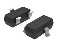 BSS123LT1资料解读:电气参数及替代型号推荐

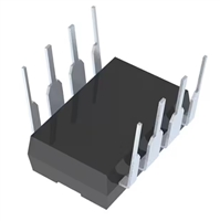 LTC1151C双通道±15V零漂移运算放大器全面解读
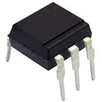 CNX36手册解读:产品特性、应用及封装引脚详解
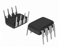 PS9552资料解读:引脚信息、电气参数
工作时间:9:00-21:00
CEO邮箱:ceo@jiepei.com
投诉邮箱:tousu@jiepei.com


 浙公网安备 33010502006866号 浙ICP备10014259号-119
营业执照ICP证
浙公网安备 33010502006866号 浙ICP备10014259号-119
营业执照ICP证


