
 5秒后页面跳转

| 型号 | 品牌 | 获取价格 | 描述 | 数据表 |
| MAX9730EVKIT+ | MAXIM |
获取价格 |
Configurable Switching Frequency |

|
| MAX9730EWP+TG45 | MAXIM |
获取价格 |
2.4W, Single-Supply, Class G Power Amplifier |
|
| MAX9736 | MAXIM |
获取价格 |
Mono/Stereo High-Power Class D Amplifier |
|
| MAX9736 | ADI |
获取价格 |
单声道/立体声大功率D类放大器 |
|
| MAX9736_V01 | MAXIM |
获取价格 |
Mono/Stereo High-Power Class D Amplifier |
|
| MAX9736A | MAXIM |
获取价格 |
Shutdown and Mute Control |
|
| MAX9736AETJ | MAXIM |
获取价格 |
Mono/Stereo High-Power Class D Amplifier |
|
| MAX9736AETJ/V | MAXIM |
获取价格 |
Mono/Stereo High-Power Class D Amplifier |
|
| MAX9736AETJ/V+ | MAXIM |
获取价格 |
Mono/Stereo High-Power Class D Amplifier |
|
| MAX9736AETJ/V+T | MAXIM |
获取价格 |
Audio Amplifier, |
|
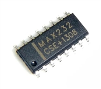 解读MAX232数据手册:全面剖析与应用推荐

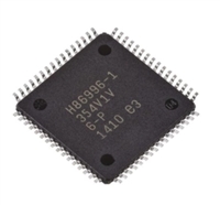 ATMEGA128数据手册解读:电气参数、引脚图
 温度传感器的常见故障及处理方法
 如何用万用表的欧姆档来辨别二极管的阴阳极
工作时间:9:00-21:00
CEO邮箱:ceo@jiepei.com
投诉邮箱:tousu@jiepei.com


 浙公网安备 33010502006866号 浙ICP备10014259号-119
营业执照ICP证
浙公网安备 33010502006866号 浙ICP备10014259号-119
营业执照ICP证


