
 5秒后页面跳转

| 生命周期: | Obsolete | 包装说明: | DIP, DIP8,.3 |
| Reach Compliance Code: | unknown | ECCN代码: | EAR99 |
| HTS代码: | 8542.39.00.01 | 风险等级: | 5.84 |
| Is Samacsys: | N | 模拟集成电路 - 其他类型: | POWER SUPPLY SUPPORT CIRCUIT |
| JESD-30 代码: | R-CDIP-T8 | 端子数量: | 8 |
| 封装主体材料: | CERAMIC, METAL-SEALED COFIRED | 封装代码: | DIP |
| 封装等效代码: | DIP8,.3 | 封装形状: | RECTANGULAR |
| 封装形式: | IN-LINE | 电源: | 1.1/5.5 V |
| 认证状态: | Not Qualified | 子类别: | Power Management Circuits |
| 最大供电电流 (Isup): | 0.1 mA | 表面贴装: | NO |
| 技术: | CMOS | 端子形式: | THROUGH-HOLE |
| 端子节距: | 2.54 mm | 端子位置: | DUAL |
| Base Number Matches: | 1 |
| 型号 | 品牌 | 获取价格 | 描述 | 数据表 |
| IMP690ACSA | IMP |
获取价格 |
レP POWER SUPPLY SUPERVISOR WITH BATTERY BACKU |

|
| IMP690ACSA | A1PROS |
获取价格 |
μP Power Supplly Superviissor wiitth Batttter |
|
| IMP690AEPA | IMP |
获取价格 |
レP POWER SUPPLY SUPERVISOR WITH BATTERY BACKU |
|
| IMP690AEPA | A1PROS |
获取价格 |
μP Power Supplly Superviissor wiitth Batttter |
|
| IMP690AESA | A1PROS |
获取价格 |
μP Power Supplly Superviissor wiitth Batttter |
|
| IMP690AESA | IMP |
获取价格 |
レP POWER SUPPLY SUPERVISOR WITH BATTERY BACKU |
|
| IMP690AMJA | IMP |
获取价格 |
レP POWER SUPPLY SUPERVISOR WITH BATTERY BACKU |
|
| IMP690AMJA | A1PROS |
获取价格 |
μP Power Supplly Superviissor wiitth Batttter |
|
| IMP692A | A1PROS |
获取价格 |
μP Power Supplly Superviissor wiitth Batttter |
|
| IMP692AC/D | IMP |
获取价格 |
レP POWER SUPPLY SUPERVISOR WITH BATTERY BACKU |
|
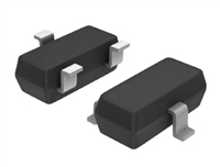 BSS123LT1资料解读:电气参数及替代型号推荐

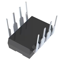 LTC1151C双通道±15V零漂移运算放大器全面解读
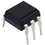 CNX36手册解读:产品特性、应用及封装引脚详解
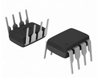 PS9552资料解读:引脚信息、电气参数
工作时间:9:00-21:00
CEO邮箱:ceo@jiepei.com
投诉邮箱:tousu@jiepei.com


 浙公网安备 33010502006866号 浙ICP备10014259号-119
营业执照ICP证
浙公网安备 33010502006866号 浙ICP备10014259号-119
营业执照ICP证


