BUS IC
DC/DC CONVERTER
MOTOR DRIVER IC
RIPPLE COUNTER
DRIVER IC
I/O IC
SENSOR IC
SENSOR INTERFACE IC
Co-integrated pressure sensor
Tilt angle sensor
ÿ
Hall sensor IC
ÿ Hall sensor IC
E910.44
FEATURES
DESCRIPTION
PINNING
Pin Name
PACKAGE
ÿ
ÿ
Supply voltage range 2.0V to 6.0V
Hall Sensor with two magnetic switching
thresholds
The IC contains a Hall sensor and the appropriate measurement
system. It detects three levels of upright magnetic field: positive,
near zero and negative. These information are provided at two bi-
nary coded outputs for any logic or uC. The sampling rate is about
10kHz (typ.) allowing fast movement detection.
Description
Supply voltage
1
VDD
VDD
OUT1
OUT2
GND
1
2
3
4
8
7
6
5
SLOW
TST_3
TST_2
TST_1/GAIN
Output: ‘0‘ -Field very positive or Low Bat
2
OUT1
‘1’- Field not positive (-> near nil or negative)
ÿ
ÿ
ÿ
ÿ
ÿ
Provides three field strength ranges:
negative, near zero and positive
Two binary coded outputs for the recognised
field strength
Extremely low integral current consumption
of<26µA in standard mode.
High measuring rate of typically 10k samples
per second in standard mode.
Slow measuring mode and/ or increased
sensitivity can be statically adjusted.
–40°C to +125°C operating temperature
SO8 package
Output: ‘0‘ -Field very negative
3
4
OUT2
GND
‘1’- Field not positive (-> near nil or negative)
Ground
In order to attain a very low average current consumption, the IC
does short measurements and holds the result at the output until
the next cycle. During the hold-phase, the IC switches to stand-by
mode with very low power consumption.
Sensitivity switching:
connect to GND: normal sensitivity;
connect to VDD: increased sensitivity;
pin not to be left open in the application
5
TST _ 1/GAIN
6
7
TST _ 2
TST _ 3
Connect to ground
Connect to ground
With two mode pins it is possible to bring th IC (statically) into a
slow mode, reducing the current consumption furthermore. The
second pin switches into a mode of increased sensitivity, where
lower magnetic fields can be detected.
Switching the trigger rate:
connect to GND: normal trigger rate;
connect to VDD: V triggerrate;
pin not to be left open in the application
8
SLOW
ÿ
ÿ
APPLICATION
ÿ
ÿ
ÿ
Motor speed and postition control
Magnetic field detection
Proximity switch
VDD
VDD
BLOCK DIAGRAM
LOW BAT
supply
Vint
Vref
ON
+
_
POS
NEG
OUT1
OUT2
Hall-
plate
µC
ctrl.
Vref.
+
_
Autozero
Measure
clock
Note ELMOS Semiconductor AG (below ELMOS) reserves the right to make changes to the product contained in this publication without notice. ELMOS assumes no responsibility for the use of any
circuits described herein, conveys no licence under any patent or other right, and makes no representation that the circuits are free of patent infringement. While the information in this publication
has been checked, no responsibility, however, is assumed for inaccuracies. ELMOS does not recommend the use of any of its products in life support applications where the failure or malfunction of
the product can reasonably be expected to cause failure of a life-support system or to significantly affect its safety or effectiveness. Products are not authorized for use in such applications.
MODE
Copyright © 2005 ELMOS Reproduction, in part or whole, without the prior written consent of ELMOS, is prohibited.
84
www.elmos.de | sales@elmos.de
elmos product catalog june 2005 85

 5秒后页面跳转


 NE5532双低噪声运算放大器:资料手册参数分析

 74LS138 3-to-8线解码器/多路复用器:资料手册参数分析
 TDA2030音频功率放大器:资料手册参数分析
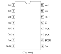 74HC595移位寄存器芯片:参数深入解析与应用实践指南


 浙公网安备 33010502006866号 浙ICP备10014259号-119
营业执照ICP证
浙公网安备 33010502006866号 浙ICP备10014259号-119
营业执照ICP证


