
 5秒后页面跳转

| 型号 | 品牌 | 获取价格 | 描述 | 数据表 |
| CTX1-1A | COOPER |
获取价格 |
Power Inductors and Transformers |

|
| CTX1-1A-R | EATON |
获取价格 |
ECONO-PACâ¢/OCTA-PAC® OCTA-PAC® PLUS Dual |
|
| CTX1-1P-R | COOPER |
获取价格 |
Surface mount magnetics that can be used as singleor coupled inductors or 1:1 transformers |
|
| CTX1-1P-R | EATON |
获取价格 |
ECONO-PACâ¢/OCTA-PAC® OCTA-PAC® PLUS Dual |
|
| CTX1-1-R | COOPER |
获取价格 |
Power Inductors and Transformers |
|
| CTX1-1-R | EATON |
获取价格 |
ECONO-PACâ¢/OCTA-PAC® OCTA-PAC® PLUS Dual |
|
| CTX1-2 | COOPER |
获取价格 |
Power Inductors and Transformers |
|
| CTX1-2A | COOPER |
获取价格 |
Power Inductors and Transformers |
|
| CTX1-2A-R | EATON |
获取价格 |
ECONO-PACâ¢/OCTA-PAC® OCTA-PAC® PLUS Dual |
|
| CTX1-2P-R | COOPER |
获取价格 |
Surface mount magnetics that can be used as singleor coupled inductors or 1:1 transformers |
|
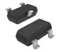 解读BAV99LT1数据手册:产品特性、电气参数及替换型号推荐

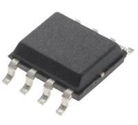 资料解析:P82B96TD引脚图说明、电气参数
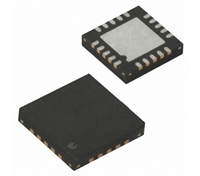 ATA6621N数据手册解读:产品特性、引脚图信息、电气参数
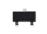 一文AO3400引脚图、参数、产品特性
工作时间:9:00-21:00
CEO邮箱:ceo@jiepei.com
投诉邮箱:tousu@jiepei.com


 浙公网安备 33010502006866号 浙ICP备10014259号-119
营业执照ICP证
浙公网安备 33010502006866号 浙ICP备10014259号-119
营业执照ICP证


