Freescale Semiconductor, Inc.
SEMICONDUCTOR TECHNICAL DATA
Order this document
by AN1207/D
ARCHIVED BY FREESCALE SEMICONDUCTOR, INC. 2005
Prepared by: David Babin and Mark Clark
Phase–locked loop (PLL) frequency synthesizers are com-
monly found in communication gear today. The carrier oscilla-
tor in a transmitter and local oscillator (LO) in a receiver are
where PLL frequency synthesizers are utilized. In some cellu-
lar phones, a synthesizer can also be used to generate 90
MHz for an offset loop. In addition, synthesizers can be used
in computers and other digital systems to create different
clocks which are synchronized to a master clock.
The MC145170 is available to address some of these
applications. The frequency capability of the newest version,
the MC145170–2, is very broad — from a few hertz to
185 MHz.
The output of a VCM is a square wave and is usually
integrated before being fed to other sections of the radio. The
VCM output can be directly used in computers and other digi-
tal equipment. The output of a VCO or VCM is typically buff-
ered, as shown.
As shown in Figure 2, the MC145170 contains a reference
oscillator, reference counter (R Counter), VCO/VCM counter
(N Counter), and phase detector. A more detailed block dia-
gram is shown in the data sheet.
HF SYNTHESIZER
The basic information required for designing a stable high–
frequency PLL frequency synthesizer is the frequencies
required, tuning resolution, lock time, and overshoot. For the
example design of Figure 3, the frequencies needed are
9.20 MHz to 12.19 MHz. The resolution (usually the same as
the frequency steps or channel spacing) is 230 kHz. The lock
time is 8 ms and a maximum overshoot of approximately 15%
is targeted. For purposes of this example, lock is considered
to be when the frequency is within about 1% of the final value.
ADVANTAGES
Frequency synthesizers, such as the MC145170, use digi-
tal dividers which can be placed under MCU control. Usually,
all that is required to change frequencies is to change the di-
vide ratio of the N Counter. Tuning in less than a millisecond
is achievable.
The MC145170 can generate many frequencies based on
the accuracy of a single reference source. For example, the
reference can be a low–cost basic crystal oscillator or a tem-
perature–compensated crystal oscillator (TCXO). Therefore,
high tuning accuracies can be achieved. Boosting of the ref-
erence frequency by 100x or more is achievable.
HF SYNTHESIZER LOW–PASS FILTER
In this design, assume a square wave output is acceptable.
To generate a square wave, a MC1658 VCM chip is chosen.
Per the transfer characteristic given in the data sheet, the
8
MC1658 transfer function, K
, is approximately 1 x 10 ra-
VCM
dians/second/volt. The loading presented by the MC1658
control input is large; the maximum input current is 350 µA.
Therefore, an active low–pass filter is used so that loading
does not affect the filter’s response. See Figure 3. In the filter,
a 2N7002 FET is chosen because it has very high transcon-
ductance (80 mmhos) and low input leakage (100 nA).
ELEMENTS IN THE LOOP
The components used in the PLL frequency synthesizer of
Figure 1 are the MC145170 PLL chip, low–pass filter, and
voltage–controlled oscillator (VCO). Sometimes a voltage–
controlled multivibrator (VCM) is used in place of the VCO.
DIVIDE VALUE
REFERENCE
REFERENCE
REFERENCE
MC145170
COUNTER
OSCILLATOR
LOW–PASS
FILTER
OSCILLATOR
f
(R COUNTER)
R
PLL
CHIP
TO
LOW–PASS
FILTER
PHASE
DETECTOR
VCO/VCM
COUNTER
(N COUNTER)
f
V
FROM
VCO/VCM
BUFFER
VCO
OUTPUT
OR
VCM
MULTIPLYING VALUE
Figure 1. PLL Frequency Synthesizer
Figure 2. Detail of the MC145170
REV 2
1/98
TN98011500
Motorola, Inc. 1998
AN1207
1
MOTOROLA
For More Information On This Product,
Go to: www.freescale.com

 5秒后页面跳转


 NE5532双低噪声运算放大器:资料手册参数分析

 74LS138 3-to-8线解码器/多路复用器:资料手册参数分析
 TDA2030音频功率放大器:资料手册参数分析
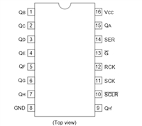 74HC595移位寄存器芯片:参数深入解析与应用实践指南


 浙公网安备 33010502006866号 浙ICP备10014259号-119
营业执照ICP证
浙公网安备 33010502006866号 浙ICP备10014259号-119
营业执照ICP证


