Max. 570 m3/h
DC axial fans
119 x 38 mm
–
Possible special versions:
(See chapter DC fans - specials)
- Speed signal
–
Material:
Housing: Die-cast aluminum
Impeller: GRP1) (PA)
–
–
Direction of air flow: Intake over struts
Direction of rotation: Clockwise, looking
towards rotor
- Go / NoGo alarm
- Alarm with speed limit
- External temperature sensor
- Internal temperature sensor
- PWM control input (standard)
- Analog control input
–
–
Connection:
Via single wires AWG 18, 20 or
AWG 22, TR 64, speed signal
and control input AWG 22
Highly efficient and smoothly
operating 3-phase fan drive
Housing with grounding lug for
screw M4 x 8 (Torx)
Highlights:
- Moisture protection
- Salt spray protection
–
Weight:
425 g
1) Fiberglass-reinforced plastic
Series 4100 N
High Performance
Nominal data
Type
m3/h
cfm
VDC
VDC
dB(A) Bel(A)
/
Watts
rpm-1
°C
Hours
Hours
4114 N/2 H7P
4114 N/2 H8P
500
570
294
336
24
24
16...30
16...30
76
78
8.5
8.9
90
9 500
-20...+75
-20...+75
57 500 / 25 000
55 000 / 22 500
97 500
92 500
¿
¡
120
11 000
4118 N/2 H7P
500
570
294
336
48
48
36...60*
36...60*
76
78
8.5
8.9
90
9 500
-20...+75
-20...+75
57 500 / 25 000
55 000 / 22 500
97 500
92 500
¿
¡
4118 N/2 H8P
120
11 000
Subject to change
* 36...72 VDC on request.
Speed control range from 500 rpm-1 up to maximum nominal speed.
Standstill at 0% PWM, maximum speed if control cable is interrupted.
To attain the specified service life, an external capacitor must be wired
between the plus and minus strands. Please note the wiring suggestion on page 16.
** Power consumption at free air flow, these values can be significantly higher in the operating point.
** Power consumption - in operation
Fan type
optimum
operating range (W)
4114 NH7P
4114 NH8P
4118 NH7P
4118 NH8P
100
160
100
160
Air performance measured according to: ISO 5801.
Installation category A, without contact protection.
Noise: Total sound power level L A ISO 103002
W
measured on a hemisphere with a radius of 2 m.
Sound pressure level L A measured at 1 m distance
p
from fan axis.
The values given are applicable only under the specified
measuring conditions and may differ depending on the
installation conditions.
In the event of deviation from the standard configuration,
the parameters must be checked after installation!
For detailed information see
http://www.ebmpapst.com/general conditions
Finger guards
from p. 242
62

 5秒后页面跳转


 NE5532双低噪声运算放大器:资料手册参数分析

 74LS138 3-to-8线解码器/多路复用器:资料手册参数分析
 TDA2030音频功率放大器:资料手册参数分析
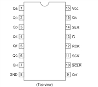 74HC595移位寄存器芯片:参数深入解析与应用实践指南


 浙公网安备 33010502006866号 浙ICP备10014259号-119
营业执照ICP证
浙公网安备 33010502006866号 浙ICP备10014259号-119
营业执照ICP证


