Cannon Trident Connectors
TNM Circular Connectors
TNM (Trident Neptune Metal) is specifically designed to meet the
needs of systems that require shielding, sealing, and the extra
durability of a metal shell. The combination of Trident contacts,
membrane seals, and the Universal Shielded Endbell* make TNM
both cost effective and easy to assemble.
TNM features nickel plated zinc alloy shells and UL 94 V-0 rated
thermoplastic insulators. All TNM receptacles are supplied with an
interfacial seal to provide sealing between connectors to IP67. In
addition, a membrane seal is available for those applications
requiring the sealing of discrete wires a the rear of the connector.
In order to seal multicore jacketed cables to connectors an endbell
is available. This has ‘O’ ring sealing to the connector and second
seal to the cable jacket. All TNM Circular Connectors are RoHS
Compliant.
*Patent pending
Product Features
Applications
• Accepts Trident signal, printed circuit, and
coaxial contacts.
• Antennas.
• Mixed signal and 30 A power contact version.
• Can be sealed to IP67.
• 360° shielding.
• Industrial electronics.
• Heavy duty equipment.
• Servo Motors.
• Robotics/ Control Panel.
• Industrial Instrumentation.
• Easy to assemble.
• Recognized under the component program of UL Inc. and CSA.
Performance Specifications
Materials and Finishes
Operating Voltage1 Up to 250 V ac rms
Contact Current Rating2 Up to 13 A; Up to 16 A with High
Conductivity Contacts;
Shell
Nickel Plated Zinc Alloy
Insulator
Coupling Ring
Seal
Black Nylon
Nickel Plated Brass
Rubber
Up to 30 A with Power Contacts;
Up to 40 A with D Sub Contacts
Operating Temperature -55°C to +105°C (-67°F to +221°F)
Insulation Resistance 5000MΩ min. at 500 V dc
Durability3 Up to 200 Mating Cycles
Environmental Sealing Up to IP67
1
2
Depends on contacts used, layout, and degree of pollution
Depends on type and number of contacts used
Flammability UL 94 V-0
3
Depends on plating and type of contacts used
Test Specifications
The table below summarizes the results of key tests performed. Data is applicable to standard connectors with standard
cotnacts. Variations may affect this data, so please consult factory for further information on your requirements.
Test
Method
Criteria of Acceptance
Dielectric Withstanding Voltage
Thermal Shock
Physical Shock
2000 V ac rms
No breakdown
No physical damage
No physical damage
No loss of continuity > 10 μsec
No physical damage
-55°C to +125°C (-67°F to +257°F), 5 cycles
40 g‘s peak, 3 axes, 6 millisecond
duration half-sine pulse
Vibration
10 g’s peak, 10-500 Hz, 9 hours
No loss of continuity > 10 μsec
Capable of mating and unmating
and meeting contact resistance requirements
Capable of mating and unmating
and meeting contact resistance requirements
Durability
200 cycles of mating and unmating
200 mating cycles max.
48 hours
Salt Spray
High Temperature Endurance
Humidty Steady State
100 hours at 85°C (+185°F),
16 hours at 105°C (+221°F)
RH 90-95%, 40°C (+104°F) , 504 hours
Insulation Resistance > 100 MΩ
Insulation Resistance > 100 MΩ
Dimensions shown in mm (inch)
Specifications and dimensions subject to change
www.ittcannon.com
52

 5秒后页面跳转


 NE5532双低噪声运算放大器:资料手册参数分析

 74LS138 3-to-8线解码器/多路复用器:资料手册参数分析
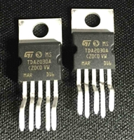 TDA2030音频功率放大器:资料手册参数分析
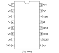 74HC595移位寄存器芯片:参数深入解析与应用实践指南


 浙公网安备 33010502006866号 浙ICP备10014259号-119
营业执照ICP证
浙公网安备 33010502006866号 浙ICP备10014259号-119
营业执照ICP证


